Re: FLASH / CIRC Custom scooter information
Posted: Thu Sep 05, 2019 2:53 pm
Can you send some pics of your motherboard cable work pls? I also have a Circ scooter and I'm a newbie. I have soldering skills.
An electric scooter community on a mission to stamp out transportation mediocrity.
https://scootertalk.org/forum/
Jcg wrote:Can you post me some picture for looking it’s a same?
I bought the same controller, can you maybe post a picture of your connections or what connection is what.Mattias93 wrote: ↑Thu Aug 22, 2019 9:29 amUPDATE
I've successfully installed this controller.
I've connected:
- Battery to controller (please note that the thinner red cable on the power line is the ignition on. I've bridged with the other red cable that goes to the battery, it won't work otherwise);
- PHASE cables;
- Haul cables;
- Original throttle 3 cables.
Notes:
- The battery has his own plug to be recharged;
- I don't have a display so I can't say what was the maximum speed, but I would say I was afraid to fall;
- I've applied thermal paste inside this controller and bridged the regenerative bridge hole to GND (but it probably doesn't work anyway);
- To make a better job I've cut all the cables from the original controller and soldered to the new one, so it's plug-n-play;
- You will need to spend some time with a tester to understand how to connect the throttle, as the cable that bridges it from the top to the ground has weird color code, as it transports also the brake cable (which I haven't connected anyway). From the throttle to this cable the color code is correct anyway, so you don't need to discover the functions of them.
- The controller doesn't fit inside the original hole, I will try something later.
- No lights wired yet, as I recall the power conversion happened on the mainboard, later on I will try to see whether I can grab some 3,3 (headlight), 5 or 12V in the BMS.
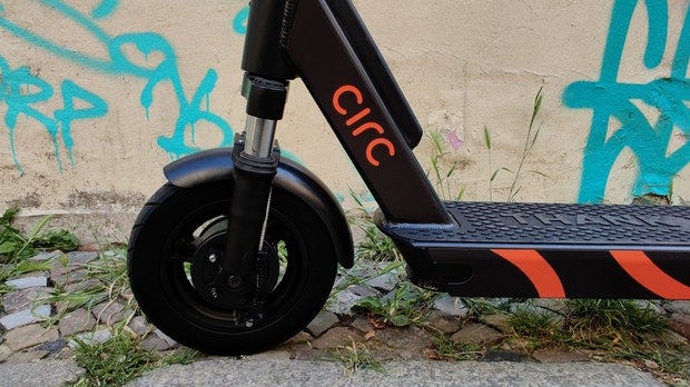
All is okMattias93 wrote: ↑Tue Jun 25, 2019 11:20 amI got my hands on one of those FLASH/CIRC company's scooter. You will need to replace control board, engine controller and accelerator, as no custom firmware or free board exists at the moment. That's not too bad as the assembly is not done well, during disassembly I've found many cut cables and an abuse of hot glue and tape. You will also want to remove the stupid LEDs on the bottom, too much Need for Speed Underground 2 for my taste. There's only one GPS module and GSM module, they are in the control board under the plastic hood, which also contains the antennas. I tried to power everything up skipping the control board but it was a no-go. I've seen that battery, control board and engine board communicate trough a RS-485 line, which receives his 3,3V from a conversion on the control board. There's an ACC cable going from Control Board to Engine Board but I don't understand what it means, I just now is shorted with the positive pole of the 36V battery. The accelerator is connected directly to the engine board, so the control board must give some sort of signal to the engine board to enable the scooter, through the RS-485 line, but I got absolutely no clue on what, how to intercept it or simulate it. Any though is welcome.
I would like to know what do you suggest as replacement engine module. The wheel with the engine has the classic 3 wires and the hall 5 wires.
Hi Mattias93